

The car suspension bible - how car suspension works including shocks, struts, springs, raising and lowering your suspension, different types of suspension, all the technologies involved, DIY car maintenance and much more.
 Win free stuff
![[Car suspension - what you need to Know]](suspension_bible_files/thesuspensionbible.gif)
 | I am in no way affiliated with any branch of the motor industry. I am just a pro-car, pro-motorbike petrolhead who is into basic maintenance. This information is the result of information-gathering, research and hands-on experience. By reading these pages, you agree to indemnify, defend and hold harmless Christopher J Longhurst, any sponsors and/or site providers against any and all claims, damages, costs or other expenses that arise directly or indirectly from you fiddling with your car or motorbike as a result of what you read here. In short: the advice here is worth as much as you are paying for it. |
Page 1 ------ Page 2
 |  |  |  |
What does it do?
Apart from your car's tyres and seats, the suspension is the prime
mechanism that separates your bum (arse for the American) from the
road. It also prevents your car from shaking itself to pieces. No
matter how smooth you think
the road is, it's a bad, bad place to propel over a ton of metal at
high speed. So we rely upon suspension. People who travel on
underground trains wish that those vehicles relied on
suspension too, but they don't and that's why the ride is so harsh.
Actually it's harsh because underground trains have no lateral
suspension to speak of. So as the rails deviate side-to-side slightly,
so does the entire train, and it's passengers. In a car, the rubber in
your tyre helps with this little problem.
In it's most basic form, suspension consists of two basic components:
Springs
These come in three types. They are coil springs, torsion bars and leaf
springs. Coil springs are what most people are familiar with, and are
actually coiled torsion bars. Leaf springs are what you would find on
most American cars up to about 1985 and almost all heavy duty vehicles.
They look like layers of metal connected to the axle. The layers are
called leaves, hence leaf-spring. The torsion bar on its own is a
bizarre little contraption which gives coiled-spring-like performance
based on the twisting properties of a steel bar. It's used in the
suspension of VW Beetles and Karmann Ghias, air-cooled Porsches (356
and 911 until 1989 when they went to springs), and the rear suspension
of Peugeot 205s amongst other cars. Instead of having a coiled spring,
the axle is attached to one end of a steel shaft. The other end is
slotted into a tube and held there by splines. As the suspension moves,
it twists the shaft along it's length, which in turn resist. Now image
that same shaft but instead of being straight, it's coiled up. As you
press on the top of the coil, you're actually inducing a twisting in
the shaft, all the way down the coil. I know it's hard to visualise,
but believe me, that's what is happening. There's a whole section
further down the page specifically on torsion bars and progressive springs.
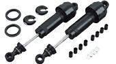
Shock absorbers
Strangely enough, absorb shocks. Actually they dampen the vertical
motion induced by driving your car along a rough surface. If your car
only had springs, it would boat and wallow along the road until you got
physically sick and had to get out. Or at least until it fell apart.
Shock absorbers perform two functions. Firstly, they absorb any
larger-than-average bumps in the road so that the shock isn't
transmitted to the car chassis. Secondly, they keep the suspension at
as full a travel as possible for the given road conditions. Shock
absorbers keep your wheels planted on the road. Without them, your car
would be a travelling deathtrap.
You want more technical terms? Technically they are called dampers.
Even more technically, they are velocity-sensitive hydraulic damping
devices - in other words, the faster they move, the more resistance
there is to that movement. They work in conjunction with the springs.
The spring allows movement of the wheel to allow the energy in the road
shock to be transformed into kinetic energy of the unsprung mass,
whereupon it is dissipated by the damper. The damper does this by
forcing gas or oil through a constriction valve (a small hole).
Adjustable shock absorbers allow you to change the size of this
constriction, and thus control the rate of damping. The smaller the
constriction, the stiffer the suspension. Phew!....and you thought they
just leaked oil didn't you?
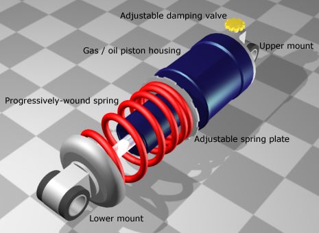
A modern coil-over-oil unit
The image above shows a typical modern coil-over-oil unit. This is an all-in-one system that carries both the spring and the shock absorber. The type illustrated here is more likely to be an aftermarket item - it's unlikely you'd get this level of adjustment on your regular passenger car. The adjustable spring plate can be used to make the springs stiffer and looser, whilst the adjustable damping valve can be used to adjust the rebound damping of the shock absorber. More sophisticated units have adjustable compression damping as well as a remote reservoir. Whilst you don't typically get this level of engineering on car suspension, most motorbikes do have preload, rebound and spring tension adjustment. See the section later on in this page about the ins and outs of complex suspension units.
Suspension Types
In their infinite wisdom, car manufacturers have set out to baffle use with the sheer number of different types of suspension available for both front and rear axles. The main groupings are dependent and independent suspension types. If you know of any not listed here, e-mail me and let me know - I would like this page to be as complete as possible.
Front suspension - dependent systems
So-called because the front wheel's suspension systems are physically linked. For everyday use, they are, in a word, shite. I hate to be offensive, but they are. There is only one type of dependent system you need to know about. It is basically a solid bar under the front of the car, kept in place by leaf springs and shock absorbers. It's still common to find these on trucks, but if you find a car with one of these you should sell it to a museum. They haven't been used on mainstream cars for years for three main reasons:
- Shimmy - because the wheels are physically linked, the beam can be set into oscillation if one wheel hits a bump and the other doesn't. It sets up a gyroscopic torque about the steering axis which starts to turn the axle left-to-right. Because of the axle's inertia, this in turn feeds back to amplify the original motion.
- Weight - or more specifically unsprung weight. Solid front axles weigh a lot and either need sturdy, heavy leaf springs or heavy suspension linkages to keep their wheels on the road.
- Alignment - simply put, you can't adjust the alignment of wheels on a rigid axis. From the factory, they're perfectly set, but if the beam gets even slightly distorted, you can't adjust the wheels to compensate.
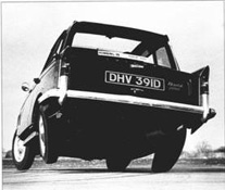
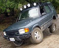 I
frequently get pulled-up on the above statements from people jumping to
defend solid-axle suspension. They usually send me pictures like this
and claim it's the best suspension system for off-road use. I have to
admit, for off-road stuff, it probably is pretty good. But let's face it; how many people with these vehicles ever
go off-road? The closest they come to having maximum wheel deflection
is when the mother double-parks the thing with one wheel on the kerb
during the school-run.......
I
frequently get pulled-up on the above statements from people jumping to
defend solid-axle suspension. They usually send me pictures like this
and claim it's the best suspension system for off-road use. I have to
admit, for off-road stuff, it probably is pretty good. But let's face it; how many people with these vehicles ever
go off-road? The closest they come to having maximum wheel deflection
is when the mother double-parks the thing with one wheel on the kerb
during the school-run.......
Picture credit: Landrover Owner's Group
| Like the site? Help Chris buy a bike. The page you're reading is free, but if you like what you see and feel you've learned something, throw me a $5 bone as a token of your appreciation. Help me buy the object of my desire. |
Front suspension - independent systems
So-named because the front wheel's suspension systems are independent of each other (except where joined by an antiroll bar) These came into existence around 1930 and have been in use in one form or another pretty much ever since then.
MacPherson Strut or McPherson strut
 This is currently, without doubt, the most widely used front suspension
system in cars of European origin. It is simplicity itself. The system
basically comprises of a strut-type spring and shock absorber combo,
which pivots on a ball joint on the single, lower arm. At the top end
there is a needle roller bearing on some more sophisticated systems.
The strut itself is the load-bearing member in this assembly, with the
spring and shock absorber merely performing their duty as oppose to
actually holding the car up. In the picture here, you can't see the shock absorber because it is encased in the black gaiter inside the spring.
This is currently, without doubt, the most widely used front suspension
system in cars of European origin. It is simplicity itself. The system
basically comprises of a strut-type spring and shock absorber combo,
which pivots on a ball joint on the single, lower arm. At the top end
there is a needle roller bearing on some more sophisticated systems.
The strut itself is the load-bearing member in this assembly, with the
spring and shock absorber merely performing their duty as oppose to
actually holding the car up. In the picture here, you can't see the shock absorber because it is encased in the black gaiter inside the spring.
The
steering gear is either connected directly to the lower shock absorber
housing, or to an arm from the front or back of the spindle (in this
case). When you steer, it physically twists the strut and shock
absorber housing (and consequently the spring) to turn the wheel.
Simple. The spring is seated in a special plate at the top of the
assembly which allows this twisting to take place. If the spring or
this plate are worn, you'll get a loud 'clonk' on full lock as the
spring frees up and jumps into place. This is sometimes confused for CV
joint knock.
![[rover 2000 front suspension]](suspension_bible_files/mcpherson_rover2000.jpg) Rover 2000 MacPherson derivative
During WWII, the British car maker Rover worked on experimental
gas-turbine engines, and after the war, retained a lot of knowledge
about them. The gas-turbine Rover T4, which looked a lot like the Rover
P6, Rover 2000 and Rover 3500, was one of the prototypes. The chassis
was fundamentally the same as the other Rovers and the net result was
the the 2000 and 3500 ended up with a very odd front suspension layout.
The gas turbine wasn't exactly small, and Rover needed as much room as
possible in the engine bay to fit it. The suspension was derived from a
normal MacPherson strut but with an added bellcrank. This allowed the
suspension unit to sit horizontally along the outside of the engine bay
rather than protruding into it and taking up space. The bellcrank
transferred the upward forces from the suspension into rearward forces
for the spring / shock combo to deal with. In the end, the gas turbine
never made it into production and the Rover 2000 was fitted with a
2-litre 4-cylinder engine, whilst the Rover 3500 was fitted with an
'evergreen' 3.5litre V8. Open the hood of either of these classics and
the engine looks a bit lost in there because there's so much room
around it that was never utilised. The image on the left shows the
Rover-derivative MacPherson strut.
Rover 2000 MacPherson derivative
During WWII, the British car maker Rover worked on experimental
gas-turbine engines, and after the war, retained a lot of knowledge
about them. The gas-turbine Rover T4, which looked a lot like the Rover
P6, Rover 2000 and Rover 3500, was one of the prototypes. The chassis
was fundamentally the same as the other Rovers and the net result was
the the 2000 and 3500 ended up with a very odd front suspension layout.
The gas turbine wasn't exactly small, and Rover needed as much room as
possible in the engine bay to fit it. The suspension was derived from a
normal MacPherson strut but with an added bellcrank. This allowed the
suspension unit to sit horizontally along the outside of the engine bay
rather than protruding into it and taking up space. The bellcrank
transferred the upward forces from the suspension into rearward forces
for the spring / shock combo to deal with. In the end, the gas turbine
never made it into production and the Rover 2000 was fitted with a
2-litre 4-cylinder engine, whilst the Rover 3500 was fitted with an
'evergreen' 3.5litre V8. Open the hood of either of these classics and
the engine looks a bit lost in there because there's so much room
around it that was never utilised. The image on the left shows the
Rover-derivative MacPherson strut.
Potted history of MacPherson: Earle S. MacPherson of General Motors developed the MacPherson strut in 1947. GM cars were originally design-bound by accountants. If it cost too much or wasn't tried and tested, then it didn't get built/used. Major GM innovations including the MacPherson Strut suspension system sat stifled on the shelf for years because innovation cannot be proven on a spreadsheet until after the product has been produced or manufactured. Consequently, Earle MacPherson went to work for Ford UK in 1950, where Ford started using his design on the 1950 'English' Ford models straight away. Today the strut type is referred to both with and without the "a" in the name, so both McPherson Strut and MacPherson Strut can be used to describe it.
Further note: Earle MacPherson should never be confused with Elle McPherson - the Australian über-babe. In her case, the McPherson Strut is something she does on a catwalk, or in your dreams if you like that sort of thing. And if you're a bloke, then you ought to....
Double wishbone suspension systems.The following three examples are all variations on the same theme. |

Historically, Triumph used transverse leaf spring suspension on their small chassis cars (Herald, Vitesse, Spitfire & GT6). In the good old British school of thought, they did this because it was cheap. The spring was bolted to the differential, rather than the chassis, and under (very) hard cornering you got jacking and tuck-under. If you got this whilst driving and panicked enough to let off the gas, or worse, step on the brake, you got massive over-steer, and pirouetted off into the nearest tree. There were plenty of complaints about this suspension system in the late 60's, so Triumph changed to a 'swing spring' system on some cars (no longer bolted to the diff), and what they called 'rotoflex' on the GT6. Again from the good old British school of thought, the replacement system was unnecessarily complicated and allegedly very fragile.
Photo credit : Triumph Herald Tricks & Tips
Speaking specifically about Corvette leaf-spring suspension.
The Corvette was not the first car to combine leaf springs with independent suspension. As well as the Triumph Herald, Fiat did something similar in the 50s with steel springs. The recent Volvo 960 Wagon (not sedan) also used fibreglass leaf springs in the rear with independent suspension. The Corvette is, as far as I know, the only vehicle that uses this setup both front and rear.
The system is definitely independent, not
like a live axle or a twist beam rear end. With dependent systems, when
one wheel moves, the other is forced to move too. The design of the
Corvette suspension is such that even though both sides are linked one
side can move without affecting the other, hence its classification as
independent. But how - what about that leaf spring? Surely if it's
attached to both sides, that makes this a dependent suspension system?
On
the older Corvettes (C2, C3, C4 rear end) the leaf spring was rigidly
clamped to the subframe in the centre. That made it act like two
separate leaf springs, one for each side. As two separate leaf springs
it, like a torsion bar, was simply an alternative to coil springs.
When
considering coil-spring type suspension, the 'third spring' is
essentially forgotten - the two visible coils are considered to be the
springing part of the suspension. Not so - there's the anti-roll bar
too. Whilst not technically a spring, it does act as a transverse
torsion bar linking both sides of the suspension together.
So the
way GM started using the tranverse leaf spring is actually very clever;
it lets one spring act as both a traditional spring and an
anti-roll. Yes - if one wheel moves, spring forces (not geometric
displacements like we see with a live axle) are applied to the other
wheel - however, in a car with an anti-roll bar the same thing happens
(see the section on anti roll bars).
The problem was that it worked well as a spring, but not so well as an
anti-roll bar, so in the end GM had to add anti-roll bars too.
Typically, aftermarket tuners will tear the leaf springs out and replace them with coil spring systems simply to make life easier. GM left many things on the Corvette with room for improvement. Leaf springs are not really a fundamental problem - typically the view is that Corvettes would be no better from the factory with coil springs. A traditional leaf spring live axle saves money because the cost of leaf springs is less than coils, trailing arms, pan hard rod etc. The Corvette has all the same suspension arms as a system with coil springs, so the only difference is the cost of the fibreglass leaf vs. the cost of the coil spring; leaf springs cost more than a coil so GM didn't do it to save money. It's not immediately clear then why they did it other than perhaps 'because they could'.
To round off this section then, here is an excellent link talking about how this suspension works - it does a far better job than I can: Fibreglass springs
Rear suspension - dependent (linked) systems
Derivatives of the 4-Bar system
There are many variations on the 4-bar systems I've illustrated above.
For example, if the four angled bars go from the axle outboard to the
chassis near the centreline, this is called a "Satchell link".
(Satchell is a US designer, who used the above linkage on some of Paul
Newmans Datsun road racers some years back.) It has certain advantages
over the above examples. Both of the these angled linkages can be
reversed to have the angled links below the axle and the parallel links
above. The roll centre will be lowered with the angled bars under the
axle, a function which is difficult to accomplish without this design.
The other variation on the "four bars" not shown are the Watts and
Jacobs bar linkages to replace the Panhard rod for lateral positioning.
Another linkage is the two parallel bars above the axle and a
triangulated link underneath - a design you will find on the Lotus 7 -
where the lower link has its base on the chassis and the apex under the
differential. Then there is the Mallock Woblink, which could be
described as half way between a Jacobs ladder and a Watts link, and
makes it possible to place the rear roll centre quite low without
sacrificing ground clearance.
Watts
links are pretty popular with the hydraulic lowrider/truck bed dancer
types. The Jacobs ladder is used almost exclusively on US midget and
sprintcar dirt track rear ends. The Mallock Woblink is used mostly on
the Mallock U2 Clubman cars in Great Britain.
de Dion suspension, or the de Dion tube
 The
de Dion tube - not part of the London underground, but rather a
semi-independent rear suspension system designed to combat the twin
evils of unsprung weight and poor ride quality in live axle systems. de
Dion suspension is a weird bastardisation of live-axle solid-beam
suspension and fully independent trailing-arm suspension. It's neither
one, but at the same time it's both. Weird! With this system, the
wheels are interconnected by a de Dion Tube, which is essentially a
laterally-telescoping part of the suspension designed to allow the
wheel track to vary during suspension movement. This is necessary
because the wheels are always kept parallel to each other, and thus
perpendicular to the road surface regardless of what the car body is
doing. This setup means that when the wheels rebound, there is also no
camber change which is great for traction, and that's the first
advantage of a de Dion Tube. The second advantage is that it
contributes to reduced unsprung weight in the vehicle because the
transfer case / differential is attached to the chassis of the car
rather than the suspension itself.
The
de Dion tube - not part of the London underground, but rather a
semi-independent rear suspension system designed to combat the twin
evils of unsprung weight and poor ride quality in live axle systems. de
Dion suspension is a weird bastardisation of live-axle solid-beam
suspension and fully independent trailing-arm suspension. It's neither
one, but at the same time it's both. Weird! With this system, the
wheels are interconnected by a de Dion Tube, which is essentially a
laterally-telescoping part of the suspension designed to allow the
wheel track to vary during suspension movement. This is necessary
because the wheels are always kept parallel to each other, and thus
perpendicular to the road surface regardless of what the car body is
doing. This setup means that when the wheels rebound, there is also no
camber change which is great for traction, and that's the first
advantage of a de Dion Tube. The second advantage is that it
contributes to reduced unsprung weight in the vehicle because the
transfer case / differential is attached to the chassis of the car
rather than the suspension itself.
Naturally, the advantages are
equalled by disadvantages, and in the case of de Dion systems, the
disadvantages would seem to win out. First off, it needs two CV joints
per axle instead of only one. That adds complexity and weight. Well one
of the advantages of not having the differential as part of the
suspension is a reduction
in weight, so adding more weight back into the system to compensate for
the design is a definite distadvantage. Second, the brakes are mounted
inboard with the calipers attached to the transfer case, which means to
change a brake disc, you need to dismantle the entire suspension system
to get the driveshaft out. (Working on the brake calipers is no walk in
the park either.) Finally, de Dion units can be used with a leaf-spring
or coil-spring arrangement. With coil spring (as shown here) it needs
extra lateral location links, such as a panhard rod, wishbones or
trailing links. Again - more weight and complexity.
de Dion
suspension was used mostly used from the mid 60's to the late 70's and
could be found on some Rovers, the Alfa Romeo Alfettas (including the
sedans and the GTV) and the GTV6, one or two Lancias a smattering of
exotic racing cars and budget sports cars or coupes.
More recently
deDion suspension has had somewhat of a renaissance in the specialist
sports car and kit car market such as those from Caterham, Westfield
and Dax. These all uniformly now use outboard brake setups for
ease-of-use, and a non-telescoping tube, usually with trailing links
and an A-bar for lateral location (rather than a Watts linkage or
Panhard rod.) Whilst a properly setup independent suspension system
will always win hands-down on poorly maintained roads, when you get on
to the track, the advantage is not so clear cut and a well set up
deDion system can often match it turn-for-turn now, espeically for
flyweight cars.
Rear suspension - independent systems
It follows, that what can be fitted to the front of a car, can be fitted to the rear to without the complexities of the steering gear. Simplified versions of all the independent systems described above can be found on the rear axles of cars. The multi-link system is currently becoming more and more popular. In advertising, it's put across as '4-wheel independent suspension'. This means all the wheels are independently mounted and sprung. There are two schools of thought as to whether this system is better or worse for handling than, for example, Macpherson struts and a twist axle. The drive towards 4-wheel independent suspension is primarily to improve ride quality without degrading handling.
The eBay problem
This paragraph may seem a little out of place but I have had a lot of problems with a couple of eBay members (megamanuals and lowhondaprelude) stealing my work, turning it into PDF files and selling it on eBay. Generally, idiots like this do a copy/paste job so they won't notice this paragraph here. If you're reading this and you bought this page anywhere other than from my website at www.carbibles.com, then you have a pirated, copyright-infringing copy. Please send me an email as I am building a case file against the people doing this. Go to www.carbibles.com to see the full site and find my contact details. And now, back to the meat of the subject....
Ford Control Blade™ Suspension
A lot of attention and marketing has been coming out of Ford recently
about their new Control Blade™ rear suspension. Details and engineering
facts are predictably sketchy but the glossy marketing brochures will
tell you this revolution in rear suspension will make your Ford Focus
handle better, grip the road better, and brake better than everything
else on the road. It warrants some investigation when they make claims
like that, but it turns out what they mean is "we've got a new
suspension system", and not much else. It actually started out its life
sometime around 1998 in Ford of Australia and I believe Holden had
something to do with it too. Since then its become far more mainstream.
So "Control Blade™" is the snappy marketing name that Ford use to
describe their new system. It sounds good, looks good on paper, and has
an aura of 21st century-ness about it. "Blade". Ooh. Cool.
The reality isn't quite so cool though - control blade is basically an
evolution of trailing-arm suspension. However its still an interesting
development and it does serve the purpose for which Ford designed it.
The primary purpose of Control Blade suspension is to increase the
interior space available in the vehicle. Most suspension systems used
in daily drivers have strut towers front and rear. In the front it's
not really a problem, but in the rear it impedes on boot (or trunk)
space. Ford wanted to give more space in the back and needed to find a
good way to remove or reduce the size of the strut towers. The result
is their Control Blade™ system which in essence separates the shock
absorber from the springs. To do this, Ford needed to use a
trailing-arm type suspension so that they didn't have swingarms up
under the wheel arches. The springs were shortened and moved inboard
and underneath. In one variation, the shock absorbers still sit
vertically but the space they take up now is hugely reduced because
they no longer have the coil springs around the outside. In the second
variation the shock absorber is a subminiature unit mounted inboard of
the springs underneath the vehicle. I'm not sure of the merits of the
super-short shock absorber but Ford seem to think it works. The control
blades themselves are basically the trailing arms which give lateral
support and provide the vertical pivot point for the entire unit.
The Ford spiel says this about Control Blade™: "It
has the key function of promoting ride and reducing road noise
transmission, while providing the freedom to let the lateral links
define toe and camber by absorbing any rearward forces and allowing the
rest of the suspension to do it's job uninterrupted. Effectively
isolating the handling components of the new IRS from the road noise
and impact harshness components of the suspension.". In English? It
means better handling and less road noise. Looking at the basic design
it's not difficult to see that this system has a much lower centre of
gravity than a Macpherson strut (for example). Lower C-of-G in a
vehicle is always a good thing. The geometry of the Control Blade™
system also provides significant 'anti-dive' under braking force, which
means a the car body will dive less when you jump on the brakes which
in turn translates into more well-behaved braking response. Lower
C-of-G, less roll and less pitch during braking all add up to better
handling, althouth whether the average driver would notice or not is a
different matter.
Another function of this system is that they've
separated the two basic functions of suspension. With the springs and
shock absorbers being mounted in different places, Ford have managed to
optimise the function of these components. It's similar in concept to
what BMW did with the telelever front suspension on motorbikes -
separating braking from suspension forces, only in the control blade
system, it separates the springing support of the suspension from the
shock reducing functions of the shock absorbers.
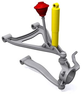
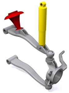
The images below are currently from other sources as I've not had the
time to render up my own just yet, but they show the basic layout of
each variation of control blade suspension and I've annotated them
accordingly.
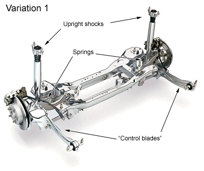
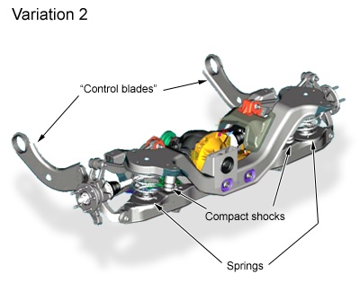
Picture credits: Ford press kit
Aftermarket work on Control Blade™ vehicles.
There's one thing worth noting about this suspension system. Because the spring and shock are in different locations, and because of the reduced or removed strut towers, it makes it very difficult to bolt-on aftermarket suspension kits to these vehicles. For the daily driver, that's probably not an issue but if you're looking at spiffing up the suspension on a Ford Focus for track days or racing, it's not going to be quite so straightforward as it is on other cars. Just so you know.
| Like the site? Help Chris buy a bike. The page you're reading is free, but if you like what you see and feel you've learned something, throw me a $5 bone as a token of your appreciation. Help me buy the object of my desire. |
Hydrolastic Suspension
If you've got this far, you'll remember that Dr. Alex Moulton
originally wanted the Mini to have Hydrolastic suspension - a system
where the front and rear suspension systems were connected together in
order to better level the car when driving.
The principle is simple. The front and rear suspension units have
Hydrolastic displacers, one per side. These are interconnected by a
small bore pipe. Each displacer incorporates a rubber spring (as in the
Moulton rubber suspension system), and damping of the system is
achieved by rubber valves. So when a front wheel is deflected, fluid is
displaced to the corresponding suspension unit. That pressurises the
interconnecting pipe which in turn stiffens the rear wheel damping and
lowers it. The rubber springs are only slightly brought into play and
the car is effectively kept level and freed from any tendency to pitch.
That's clever enough, but the fact that it can do this without
hindering the full range of motion of either suspension unit is even
more clever, because it has the effect of producing a soft ride.
Pictures and images of anything to do with hydrolastic suspension are
few and far between now, so you'll have to excuse the plagiarism of the
following image. The animation below shows the self-leveling effect -
notice the body stays level and doesn't pitch.
But what happens when the front and rear wheels encounter bumps or dips
together? One cannot take precedent over the other, so the fluid
suspension stiffens in response to the combined upward motion and,
while acting as a damper, transfers the load to the rubber springs
instead, giving a controlled, vertical, but level motion to the car.
Remember I said the units were connected with a small bore
pipe? The restriction of the fluid flow, imposed by this pipe, rises
with the speed of the car. This means a steadier ride at high speed,
and a softer more comfortable ride at low speed.
Hydrolastic
suspension is hermetically sealed and thus shouldn't require much, if
any, attention or maintenance during its normal working life. Bear in
mind that hydrolastic suspension was introduced in 1964 (on the
prototype BMC ADO16) and you'd be lucky to find a unit today that has
had any work done to it.
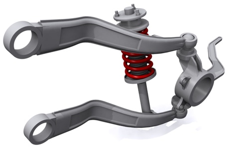
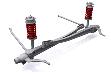
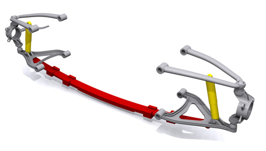
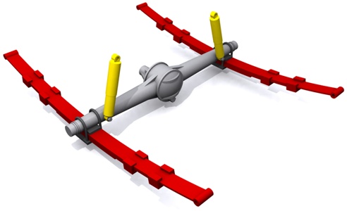
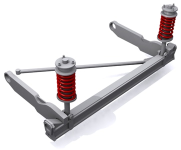
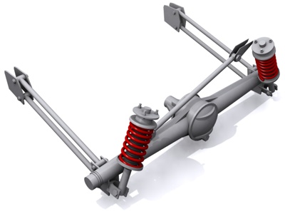
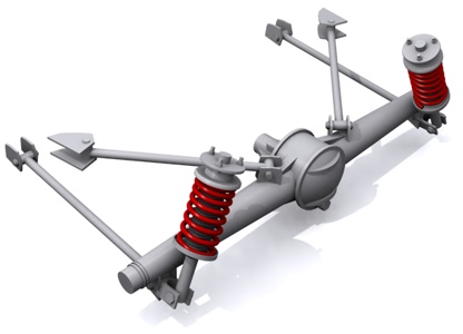
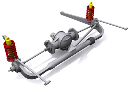
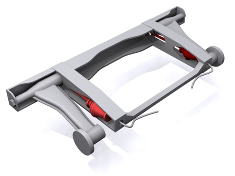
The image below shows a typical lateral installation for hydrolastic
rear suspension. The suspension swingarms are attached to the main
subframe. The red cylinders are the displacer units containing the
fluid and the rubber spring. The pipes leading from the units can be
seen and they would connect to the corresponding units at the front of
the vehicle.
Hydrolastic suspension shouldn't be confused with Citroën's
hydropneumatic suspension (see below). That system uses a hydraulic
pump that raises and lowers the car to different heights. Sure it's a
superior system but it's also a lot more costly to manufacture and
maintain. That's due in part to the fact that they don't use o-rings as
seals; the pistons and bores are machined to incredible tolerances
(microns), that it makes seals unnecessary. Downside : if something
leaks, you need a whole new cylinder assembly.
Hydrolastic was eventually refined into Hydragas suspension.......
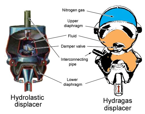
Hydragas Suspension
Hydragas is an evolution of Hydrolastic, and essentially, the design and installation of the system is the same. The difference is in the displacer unit itself. In the older systems, fluid was used in the displacer units with a rubber spring cushion built-in. With Hydragas, the rubber spring is removed completely. The fluid still exists but above the fluid there is now a separating membrane or diaphragm, and above that is a cylinder or sphere which is charged with nitrogen gas. The nitrogen section is what has become the spring and damping unit whilst the fluid is still free to run from the front to the rear units and back.
Hydragas suspension was famously used in the 1986 Porsche 959 Rally car
that entered the Paris-Dakar Rally, and today you can find it on the
MGF Roadster.
There are a lot of resources on Hydragas available at one of the MGF club sites on the internet:
http://www.mgfcar.de/hydragas
Page 1 ------ Page 2
| | | |
| These pages were last updated on 9th September 2008. Copyright © Chris Longhurst 1994 - 2008 unless otherwise noted. The author will respond expeditiously to any intellectual property infringement. Reproduction in whole or in part in any form or medium without express written permission of Chris Longhurst is prohibited. Important Copyright info. |